By Jason Thompson
Updated Mar 24, 2022
Many low‑voltage circuits—such as dimmer switches, radio volume controls, motor speed regulators, and handheld tools—require multiple voltage levels, yet they often rely on a single 12‑volt battery. By adding a simple voltage divider, or voltage reducer, you can easily create adjustable output levels from that single source.
Connect the circuit to the 12‑volt battery and switch it on. Set your multimeter to the resistance (ohms) function. Place the black probe on the battery’s negative terminal and the red probe on the positive terminal. The reading is the total resistance of the entire circuit.
Locate either wire that runs from the battery case to the rest of the circuit and cut it about 1 inch from the case. It does not matter which wire is cut; the goal is to create a splice point for the voltage reducer.
Use wire strippers to remove roughly ½ inch of insulation from each end of the cut wire.
With an emery board, gently file the leads of the variable resistor. This removes any rust or oil that may have accumulated and improves solder flow.
Insert the variable resistor leads into the designated holes on the miniature circuit board. Place the bare end of the cut battery wire into the hole adjacent to one of the resistor leads.
Heat the soldering iron and apply solder to the joint where the battery wire meets the resistor lead. Allow the solder to melt and coat both conductors, then lift the iron and let the joint set before moving on.
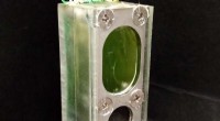
Insert the bare end of the wire that leads to the rest of the circuit into the hole next to the other resistor lead. Solder this second connection in the same manner. The voltage reducer is now integrated into the circuit. Mount the PCB to a case or panel for a tidy finish. Adjust the variable resistor to 0 % to restore the full 12‑volt output.
To determine the resistance range your variable resistor must cover, use the following quick formula:
Rvar = (12 V ÷ Vmin) × Rcircuit – Rcircuit
Where Vmin is the lowest voltage you need and Rcircuit is the resistance measured in Step 1. The result is the minimum resistance the variable resistor should be capable of providing.